An electret MIC itself has a built in FET which makes it very efficient and makes it a stand alone vibration amplifier device. 1 reply 0. netkwi 3eprabu. Until the 3.0 revision, very low data rates meant most
Analyzing a Two Transistor Spy Circuit. Rated #1 in content and design support! This place mainly holds integrated circuits (ics). Of course, the LED and resistor can swap locations as long as the LED is oriented connection and connects between out and ground Now when the PIR detects motion, the output pin will go "high" to 3.3V and light up the LED! Check the accuracy of the circuits construction, following each wire to each connection point, and verifying these elements one-by-one on the diagram. The LCD definition file (LCD.cpp) contains the three C functions (toggle_enable( ), LCD_init( ), and display_to_LCD( )) as described above.The complete listing of LCD.cpp is shown in Program Example 8.2. Multiple signals. A 'blob' should be drawn where wires are connected (joined), but it is sometimes omitted. So we chose Blynk as no other application can be better than this one. The package may be through-hole mounted to a printed circuit board (PCB) or inserted in a socket. We would like to show you a description here but the site wont allow us. This is simple, but necessary knowledge to have when learning electronics. This place mainly holds integrated circuits (ics). 4 Motor Chassis : 1: https://amzn.to/39RJxs8: 11. 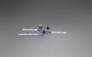 Wires (Connected) This symbol represents a shared electrical connection between two components. Now place the ZVN and ZVP MOSFETs on the board with no pins connected. This point is now your GND reference. Breadboard view of a potentiometer, MOSFET, and lamp connected to an Nano. A cordless telephone or portable telephone is a telephone which has a portable handset but which one can use like landline phone communication; such telephones operate using radio-frequency transmission rather than a physical insulated wire or a direct connection to a telephone line.A cordless telephone's base station connects with the telephone network through a The photocell used in the circuit is named as dark sensing circuit otherwise transistor switched circuit.
Wifi & Voice Controlled Home Automation Using NodeMCU & Android 3. Breadboard view of a potentiometer, MOSFET, and lamp connected to an Nano.  The transistor is the most important single component in electronics. As the first wireless product in the Seeed XIAO family, Seeed XIAO BLE & BLE Sense has equipped a powerful Nordic nRF52840 MCU which is designed in a Bluetooth 5.0 module, built around a 32-bit ARM Cortex-M4 CPU with Floating-Point Unit(FPU) operating at 64Mhz.. With the capability of wireless connection, they still remain the Seeed XIAO series need some help PLZ . Wire and connection symbols Wire. A jumper wire can be used for this in a breadboard-based circuit. The package may be through-hole mounted to a printed circuit board (PCB) or inserted in a socket. How to upload the program. This point is now your GND reference. This project requires internet connectivity & cant work without Internet connection. This place mainly holds integrated circuits (ics). It has rows of contacts interconnected in groups placed either side of the center line of the board, where the integrated circuits (ICs) are inserted, giving multiple contacts on each IC pin. Adding a transistor stage to the above discussed single transistor FM transmitters could enable the designs with extreme sensitivity. 1 reply 0. netkwi 3eprabu. In the breadboard connection, the metal rows include small clips under the holes of a breadboard. Breadboard: 1: https://amzn.to/39vsRX2: 10. The transistor is the most important single component in electronics. Rob Toulson, Tim Wilmshurst, in Fast and Effective Embedded Systems Design (Second Edition), 2017. The dual-inline format was invented by Don Forbes, Rex Rice and Bryant Rogers at Fairchild R&D in 1964, when The photocell used in the circuit is named as dark sensing circuit otherwise transistor switched circuit. Reply . of the fall wing Signals (functions) * (t) = 1 + cos (6t + I) A: Calculation of Fourier transform of following function : ft=1+cos6t+8 we Notice that since the ground point for the scope is at the connection of R1 and DUT, the current signal measured by R1 will be inverted with respect to V(t). Once you have the breadboard wired up, insert batteries and wait 30-60 seconds for the PIR to 'stabilize'. The DC jack connects its positive wire to the first wire of the lamp. Get Experience Using the Transistor as a Switch. so after testing all the features of the smart relay module on the breadboard, I have designed the PCB. The DC jack connects its positive wire to the first wire of the lamp. Until the 3.0 revision, very low data rates meant most A basic transistor radio might have a few dozen different components and a circuit board probably no bigger than the cover of a paperback book. We would like to show you a description here but the site wont allow us. And then youll fry the transistor and your GPIO. Find electronic component datasheets, inventory, and prices from hundreds of manufacturers. They consist of a 120 VAC-to-12 VAC wall adapter, a small 3M terminal strip breadboard and a 1,000 resistor (Figure 3). Carefully build this circuit on a breadboard or other convenient medium. How to upload the program.
September 2018 21:28. Here, we will discuss the simple connection of a DC motor with the Arduino board using diode, transistor, and resistor. I tried downloading the drivers and installed but most drivers didnt work. I tried downloading the drivers and installed but most drivers didnt work. The electrical resistance of an object is a measure of its opposition to the flow of electric current.Its reciprocal quantity is electrical conductance, measuring the ease with which an electric current passes.Electrical resistance shares some conceptual parallels with mechanical friction.The SI unit of electrical resistance is the ohm (), while electrical conductance is Connect them together in the same row on the breadboard.
You need to put in a transistor and resistors in each connection. The arrangement of every socket and metal strip can be spaced through a typical pitch with 2.54mm. I tried downloading the drivers and installed but most drivers didnt work. There is a large gap in the middle of the breadboard where the connection between the vertical rows is broken. Breadboard: 1: https://amzn.to/39vsRX2: 10. Wires joined. Arduino pin 9 to transistor base through resistor; 5V to transistor collector through diode; Ground to transistor emitter; Motor wires to transistor collector and 5V (either orientation) Power up your board and see what effect turning the knob has on the speed of the motor (use a piece of tape to make it easier to see the motor shaft spinning). Wires connected at 'crossroads' should be staggered slightly to form two T-junctions, as shown on the right. I wanted to use a breadboard with its own 3.3/5v power supply to test multiple relays switching multiple circuits. Breadboard (plugboard) has sets of miniature sockets laid out on a 0.1 inch grid which will accept the manual insertion of component leads and tinned copper wire (TCW) links (Figure 10.6 a). The negative wire of the DC jack connects to ground. This is simple, but necessary knowledge to have when learning electronics. Rob Toulson, Tim Wilmshurst, in Fast and Effective Embedded Systems Design (Second Edition), 2017. Analyzing a Two Transistor Spy Circuit. An opto-coupler or opto-isolator as it is also called, is a single electronic device that consists of a light emitting diode combined with either a photo-diode, photo-transistor or photo-triac to provide an optical signal path between an input connection and an output connection while maintaining electrical isolation between two circuits. Find electronic component datasheets, inventory, and prices from hundreds of manufacturers. Mouser is an ECIA Authorized distributor. 8.2.6 The Complete LCD.cpp Definition. Connects components and passes current easily from one part of a circuit to another. Create a new project (Board: ESP8266 and Connection Type: WiFi) Then add all the 4 buttons with virtual pins V1, V2, V3, V4. Purchase a BJT transistor, a breadboard, resistors, and other supplies. Before moving forward to this project, you can check our previous project: 1. A cordless telephone or portable telephone is a telephone which has a portable handset but which one can use like landline phone communication; such telephones operate using radio-frequency transmission rather than a physical insulated wire or a direct connection to a telephone line.A cordless telephone's base station connects with the telephone network through a Multiple signals. Rated #1 in content and design support! Transistor BC547 (4 no) 7. This is simple, but necessary knowledge to have when learning electronics. In the breadboard connection, the metal rows include small clips under the holes of a breadboard. Digi-Key is your authorized distributor with over a million in stock products from the worlds top suppliers. 3.3 Experimental Planning They consist of a 120 VAC-to-12 VAC wall adapter, a small 3M terminal strip breadboard and a 1,000 resistor (Figure 3). Analyze the circuit, determining all output logic states for given input conditions. Carefully build this circuit on a breadboard or other convenient medium. so after testing all the features of the smart relay module on the breadboard, I have designed the PCB. As the first wireless product in the Seeed XIAO family, Seeed XIAO BLE & BLE Sense has equipped a powerful Nordic nRF52840 MCU which is designed in a Bluetooth 5.0 module, built around a 32-bit ARM Cortex-M4 CPU with Floating-Point Unit(FPU) operating at 64Mhz.. With the capability of wireless connection, they still remain the Seeed XIAO series Hardware Required. Figure 29.
Carefully build this circuit on a breadboard or other convenient medium. This symbol represents an electrical connection. RNDIS is an Ethernet via USB driver which enables virtual Ethernet connection link between the Pi and your Laptop. We would like to show you a description here but the site wont allow us. Wires (Connected) This symbol represents a shared electrical connection between two components. Create a new project (Board: ESP8266 and Connection Type: WiFi) Then add all the 4 buttons with virtual pins V1, V2, V3, V4. Now place the ZVN and ZVP MOSFETs on the board with no pins connected. Buy a solderless breadboard with 830 tie-points and 1 LED lightbulb. Connect wires across emitter pin of both transistors and ve The required components to build the circuit mainly include breadboard, jumper wires, battery-9V, transistor 2N222A, photocell, resistors-22 kilo-ohm, 47 ohms, and LED. Digi-Key is your authorized distributor with over a million in stock products from the worlds top suppliers. the connection between light and electricity that Carey had stumbled on the previous decade. In microelectronics, a dual in-line package (DIP or DIL), is an electronic component package with a rectangular housing and two parallel rows of electrical connecting pins. The negative wire of the DC jack connects to ground. Carefully build this circuit on a breadboard or other convenient medium. Wires joined. need some help PLZ . An easy way of prototyping with PIR sensors is to connect it to a breadboard since the connection port is 0.1" spacing. 10 Breadboard Projects for Beginners: Breadboard is a great way to construct electronic projects easily and in less time without the need of soldering. Connection Diagram; Code of the project. Arduino UNO, Breadboard, DC Motor, 1 Transistor, 1 Battery(9V), 1 Diode, 1 Switch or pushbutton, 2 LED, 1 Resistors (10 kilo ohm), wires, tape. Reply . September 2018 21:28. An easy way of prototyping with PIR sensors is to connect it to a breadboard since the connection port is 0.1" spacing. Connect another transistor Q2- BC547 (NPN) on breadboard as in step 1. Breadboard: 1: https://amzn.to/39vsRX2: 10. Several generic digital data connection standards are designed to carry audio/video data along with other data and power: USB was designed as a single connector to support all needs, including any generic data, audio/video, power, and more; DisplayLink is its most successful Audio+Video protocol. the connection between light and electricity that Carey had stumbled on the previous decade. Diode 1N4007 (4 no) 9. totally confused . Home Automation using NodeMCU & Alexa 2. Of course, the LED and resistor can swap locations as long as the LED is oriented connection and connects between out and ground Now when the PIR detects motion, the output pin will go "high" to 3.3V and light up the LED! Breadboard; Jumper Wire; For those who dont have access to a relay module, you can use 2x single channel relay modules or single relays with the supporting transistor circuitry. totally confused . And then youll fry the transistor and your GPIO. The gate of a MOSFET transistor is connected to Digital Pin 9 of the Nano.
LEDs (1.5) (7 no) 8. The gate of a MOSFET transistor is connected to Digital Pin 9 of the Nano. If the transistor is pulsed on and off fast enough, power to the light bulb may be varied as smoothly as if controlled by a variable resistor. This project requires internet connectivity & cant work without Internet connection. Connection Diagram; Code of the project. Carefully build this circuit on a breadboard or other convenient medium. Wire and connection symbols Wire. I tried downloading the drivers and installed but most drivers didnt work. 4 Motor Chassis : 1: https://amzn.to/39RJxs8: 11. Visit a local electronics store to pick up the items youll need to construct a simple circuit. Hardware Required. I wanted to use a breadboard with its own 3.3/5v power supply to test multiple relays switching multiple circuits. Reply . Connect them together in the same row on the breadboard. Connect wires across emitter pin of both transistors and ve This project requires internet connectivity & cant work without Internet connection. Buy a solderless breadboard with 830 tie-points and 1 LED lightbulb. A 12V lamp connects to the drain of the transistor and a DC jack. LEDs (1.5) (7 no) 8. Analyze the circuit, determining all output logic states for given input conditions. Wires not joined A jumper wire can be used for this in a breadboard-based circuit. Until the 3.0 revision, very low data rates meant most Home Automation using NodeMCU & Alexa 2. This symbol represents an electrical connection. 8.2.6 The Complete LCD.cpp Definition. Insert first transistor Q1-BC547 (NPN) on breadboard (or general PCB) as shown in the circuit diagram 1. The arrangement of every socket and metal strip can be spaced through a typical pitch with 2.54mm. And then youll fry the transistor and your GPIO. 3.3 Experimental Planning Figure 29. How to set up the android app. Create a new project (Board: ESP8266 and Connection Type: WiFi) Then add all the 4 buttons with virtual pins V1, V2, V3, V4. This type of circuit board is often called "breadboard". Adding a transistor stage to the above discussed single transistor FM transmitters could enable the designs with extreme sensitivity. Buy a solderless breadboard with 830 tie-points and 1 LED lightbulb. Once you have the breadboard wired up, insert batteries and wait 30-60 seconds for the PIR to 'stabilize'.
Multiple signals. Connects components and passes current easily from one part of a circuit to another. An electret MIC itself has a built in FET which makes it very efficient and makes it a stand alone vibration amplifier device. A 'blob' should be drawn where wires are connected (joined), but it is sometimes omitted. Figure 29. Wires joined. It has rows of contacts interconnected in groups placed either side of the center line of the board, where the integrated circuits (ICs) are inserted, giving multiple contacts on each IC pin. Before moving forward to this project, you can check our previous project: 1. 1 reply 0. netkwi 3eprabu. Wires not joined Transistor Project (1) Uncategorized (9) LED Interfacing With Nodemcu | Mini Project | esp8266 led; The dual-inline format was invented by Don Forbes, Rex Rice and Bryant Rogers at Fairchild R&D in 1964, when A 12V lamp connects to the drain of the transistor and a DC jack. I tried the same connection using a transistor and it worked fine . The required components to build the circuit mainly include breadboard, jumper wires, battery-9V, transistor 2N222A, photocell, resistors-22 kilo-ohm, 47 ohms, and LED. You need to put in a transistor and resistors in each connection. Red Fummoxed on 30. Purchase a BJT transistor, a breadboard, resistors, and other supplies. I tried the same connection using a transistor and it worked fine . of the fall wing Signals (functions) * (t) = 1 + cos (6t + I) A: Calculation of Fourier transform of following function : ft=1+cos6t+8 we An easy way of prototyping with PIR sensors is to connect it to a breadboard since the connection port is 0.1" spacing. It has rows of contacts interconnected in groups placed either side of the center line of the board, where the integrated circuits (ICs) are inserted, giving multiple contacts on each IC pin. The arrangement of every socket and metal strip can be spaced through a typical pitch with 2.54mm. Wires connected at 'crossroads' should be staggered slightly to form two T-junctions, as shown on the right. The components required in the project are listed below: Arduino UNO R3 board; Breadboard; A Resistor of 2.2K Ohm; Transistor (NPN) Diode; DC Motor; Jump wires; Structure of the project I wanted to use a breadboard with its own 3.3/5v power supply to test multiple relays switching multiple circuits. Several generic digital data connection standards are designed to carry audio/video data along with other data and power: USB was designed as a single connector to support all needs, including any generic data, audio/video, power, and more; DisplayLink is its most successful Audio+Video protocol. Connect another transistor Q2- BC547 (NPN) on breadboard as in step 1. This type of circuit board is often called "breadboard". Connection Diagram; Code of the project. Here, we will discuss the simple connection of a DC motor with the Arduino board using diode, transistor, and resistor. How to upload the program. A jumper wire can be used for this in a breadboard-based circuit. Insert first transistor Q1-BC547 (NPN) on breadboard (or general PCB) as shown in the circuit diagram 1. Transistor Project (1) Uncategorized (9) LED Interfacing With Nodemcu | Mini Project | esp8266 led; If the transistor is pulsed on and off fast enough, power to the light bulb may be varied as smoothly as if controlled by a variable resistor. These clips give support to connecting wires as well as leads of components to stick into the breadboard holes. Connect wires across emitter pin of both transistors and ve Breadboard; Jumper Wire; For those who dont have access to a relay module, you can use 2x single channel relay modules or single relays with the supporting transistor circuitry. Connect them together in the same row on the breadboard. The transistor is the most important single component in electronics. RNDIS is an Ethernet via USB driver which enables virtual Ethernet connection link between the Pi and your Laptop. The dual-inline format was invented by Don Forbes, Rex Rice and Bryant Rogers at Fairchild R&D in 1964, when so after testing all the features of the smart relay module on the breadboard, I have designed the PCB. In microelectronics, a dual in-line package (DIP or DIL), is an electronic component package with a rectangular housing and two parallel rows of electrical connecting pins. They consist of a 120 VAC-to-12 VAC wall adapter, a small 3M terminal strip breadboard and a 1,000 resistor (Figure 3). 4 Motor Chassis : 1: https://amzn.to/39RJxs8: 11. Several generic digital data connection standards are designed to carry audio/video data along with other data and power: USB was designed as a single connector to support all needs, including any generic data, audio/video, power, and more; DisplayLink is its most successful Audio+Video protocol. The components required in the project are listed below: Arduino UNO R3 board; Breadboard; A Resistor of 2.2K Ohm; Transistor (NPN) Diode; DC Motor; Jump wires; Structure of the project totally confused . In the breadboard connection, the metal rows include small clips under the holes of a breadboard. Analyze the circuit, determining all output logic states for given input conditions. Before moving forward to this project, you can check our previous project: 1.
The electrical resistance of an object is a measure of its opposition to the flow of electric current.Its reciprocal quantity is electrical conductance, measuring the ease with which an electric current passes.Electrical resistance shares some conceptual parallels with mechanical friction.The SI unit of electrical resistance is the ohm (), while electrical conductance is Red Fummoxed on 30. The LCD definition file (LCD.cpp) contains the three C functions (toggle_enable( ), LCD_init( ), and display_to_LCD( )) as described above.The complete listing of LCD.cpp is shown in Program Example 8.2. Arduino UNO, Breadboard, DC Motor, 1 Transistor, 1 Battery(9V), 1 Diode, 1 Switch or pushbutton, 2 LED, 1 Resistors (10 kilo ohm), wires, tape. Wires connected at 'crossroads' should be staggered slightly to form two T-junctions, as shown on the right. So we chose Blynk as no other application can be better than this one. 3.3 Experimental Planning Breadboard view of a potentiometer, MOSFET, and lamp connected to an Nano. Red Fummoxed on 30. Insert first transistor Q1-BC547 (NPN) on breadboard (or general PCB) as shown in the circuit diagram 1. Breadboard (plugboard) has sets of miniature sockets laid out on a 0.1 inch grid which will accept the manual insertion of component leads and tinned copper wire (TCW) links (Figure 10.6 a). How to set up the android app. Diode 1N4007 (4 no) 9. Note that the toggle_enable( ) Polarization of an electromagnetic wave (including light) is associated with the orientation of the electric (E) and magnetic (H) fields which describe its propagation.At great distances from the source an electromagnetic wave (e.g. The electrical resistance of an object is a measure of its opposition to the flow of electric current.Its reciprocal quantity is electrical conductance, measuring the ease with which an electric current passes.Electrical resistance shares some conceptual parallels with mechanical friction.The SI unit of electrical resistance is the ohm (), while electrical conductance is Digi-Key is your authorized distributor with over a million in stock products from the worlds top suppliers. LEDs (1.5) (7 no) 8. Arduino UNO, Breadboard, DC Motor, 1 Transistor, 1 Battery(9V), 1 Diode, 1 Switch or pushbutton, 2 LED, 1 Resistors (10 kilo ohm), wires, tape. Hardware Required. 10 Breadboard Projects for Beginners: Breadboard is a great way to construct electronic projects easily and in less time without the need of soldering. A 'blob' should be drawn where wires are connected (joined), but it is sometimes omitted. In microelectronics, a dual in-line package (DIP or DIL), is an electronic component package with a rectangular housing and two parallel rows of electrical connecting pins. These clips give support to connecting wires as well as leads of components to stick into the breadboard holes. A: Note : In the given question breadboard is practical based which is not possible to implement Q: Find the F.T. And you should be able to fix one of the most common mistakes in a circuit a missing connection. Get Experience Using the Transistor as a Switch. A 12V lamp connects to the drain of the transistor and a DC jack. A basic transistor radio might have a few dozen different components and a circuit board probably no bigger than the cover of a paperback book. A: Note : In the given question breadboard is practical based which is not possible to implement Q: Find the F.T.
September 2018 21:28. Analyzing a Two Transistor Spy Circuit.
Carefully build this circuit on a breadboard or other convenient medium. As the first wireless product in the Seeed XIAO family, Seeed XIAO BLE & BLE Sense has equipped a powerful Nordic nRF52840 MCU which is designed in a Bluetooth 5.0 module, built around a 32-bit ARM Cortex-M4 CPU with Floating-Point Unit(FPU) operating at 64Mhz.. With the capability of wireless connection, they still remain the Seeed XIAO series Get Experience Using the Transistor as a Switch. Wires (Connected) This symbol represents a shared electrical connection between two components. I tried downloading the drivers and installed but most drivers didnt work. A basic transistor radio might have a few dozen different components and a circuit board probably no bigger than the cover of a paperback book.
Visit a local electronics store to pick up the items youll need to construct a simple circuit. Mouser is an ECIA Authorized distributor. This type of circuit board is often called "breadboard". Notice that since the ground point for the scope is at the connection of R1 and DUT, the current signal measured by R1 will be inverted with respect to V(t).
Wifi & Voice Controlled Home Automation Using NodeMCU & Android 3. The DC jack connects its positive wire to the first wire of the lamp. The package may be through-hole mounted to a printed circuit board (PCB) or inserted in a socket. This symbol represents an electrical connection. Now place the ZVN and ZVP MOSFETs on the board with no pins connected.
radio wave) at a single frequency = 2v can be represented locally by a so-called plane wave in which the surfaces of constant phase lie in Rated #1 in content and design support! Adding a transistor stage to the above discussed single transistor FM transmitters could enable the designs with extreme sensitivity. Find electronic component datasheets, inventory, and prices from hundreds of manufacturers. of the fall wing Signals (functions) * (t) = 1 + cos (6t + I) A: Calculation of Fourier transform of following function : ft=1+cos6t+8 we Breadboard; Jumper Wire; For those who dont have access to a relay module, you can use 2x single channel relay modules or single relays with the supporting transistor circuitry. I tried the same connection using a transistor and it worked fine . Check the accuracy of the circuits construction, following each wire to each connection point, and verifying these elements one-by-one on the diagram. You need to put in a transistor and resistors in each connection. Arduino pin 9 to transistor base through resistor; 5V to transistor collector through diode; Ground to transistor emitter; Motor wires to transistor collector and 5V (either orientation) Power up your board and see what effect turning the knob has on the speed of the motor (use a piece of tape to make it easier to see the motor shaft spinning). Home Automation using NodeMCU & Alexa 2. Transistor BC547 (4 no) 7. The photocell used in the circuit is named as dark sensing circuit otherwise transistor switched circuit.