This Paper. Therefore, the essential components of a generator are: Calculate the emf generated in the armature, what would be the emf if the winding is wave connected. If the conductor is provided with a closed path, the induced current will circulate within the path. Therefore, Eg = PNZ / 60A For simplex lap winding, number of parallel paths is equal to the number of poles (i.e. 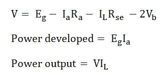 Z Total number of armature conductors. by Atif Syed. A PROCESS REPORT FOR ANGLOGOLD ASHANTI.
  Enter the email address you signed up with and we'll email you a reset link. When a conductor or a coil is rotated in a magnetic field by the prime mover, it E.M.F. View Pblms in EMF eqn of DC Gen.pdf from EEE 2003 at Vellore Institute of Technology. SkyMan Vichheka. A 4 pole, 1500rpm DC generator has lap wound armature conductors having 24 slots with 10 conductors per slot. Dc generator emf equation.
  Linear Control System Analysis and Design With Matlab. In fact, when the machine is being assembled, the workmen usually do not know whether it is a d.c. generator or motor. Download Free PDF Download PDF Download Free PDF View PDF. E.M.F. = flux per pole in weber. The working principle of an electric generator is based on the principle of the faradays law of electromagnetic induction, it states that whenever a conductor is placed in a moving magnetic field, an e.m.f. 7. EMF Equation of a DC Generator. 2. It is done specifically to know the internal and external characteristics. Simple wave wound generator. Explanation: The air gap under the poles in a dc machine is almost uniform and further, the pole shoes are wider than in a synchronous machine (pole-arc is about 70% of the pole-pitch). The derivation of EMF equation for DC generator has two parts: 1. If the armature reaction is neglected, decrease in V a should be linear and equal to the voltage drop across R a and carbon brushes.
E.M.F Equation of Transformer: The primary winding draws a current when it is connected to an alternating voltage source this sinusoidal current produces a sinusoidal flux that can be expressed as: 1-2) consists of a wire loop placed so that it can be rotated in a stationary magnetic field. The gas servo system of gas generator, pneumatic servo valve and gas motor was adopted. Induced EMF of oneconductor 2. INTRODUCTION TO DC GENERATOR GENERATOR is machine that converts mechanical energy to electrical energy. What is Electromotive Force Formula? Following is the formula for electromotive force: = V + Ir Where, V is the voltage of the cell I is the current across the circuit r is the internal resistance of the cell is the electromotive force What is the unit of EMF? The unit for electromotive force is Volt. G g k m a ZP n k n a ZP E = = = = 60 2 Prof., SELECT, VIT, Vellore Content Problems in E.M.F. by Simphiwe Nzuza. If the DC Machine is working as a Motor, the induced emf is given by the equation shown below: 13 Full PDFs related to this paper. depends upon the lengths of the conductor, the magnetic field strength, and the speed at which the coil rotates. The bearing must always be lubricated properly for smooth operation and long life of generator. calculated from the emf equation of dc generator. 8. Download Download PDF.  Lets assume that a generator has Z total conductors that are designed so that all parallel routes are always in series. l = active conductor length. Full PDF Package Download Full PDF Package. Are you having problems with citing sources? and 16 conductors per slot. Download Free PDF Download PDF Download Free PDF View PDF. Open navigation menu. Known : The rate of change of initial magnetic flux ( B . Theory and Problems of Applied Physics. When a voltage (an electro-motive force) is applied to a motor's armature, current begins to flow, creating a magnetic force which causes the armature to rotate. Line reactors for harmonic reduction. SOLUTION MANUAL. value of fundamental frequency EMF generated in a conductor is, e c 1 = f 1 / 2 = 2.22 f 1. A short summary of this paper. Determine the induced emf induced. Matrix Converter Fed Brushless Dc Motor Using Field Programmable Gate Array. This Paper. Search: Emf Calculator. Scribd is the world's largest social reading and publishing site. a = number of armature current paths. Induced emf of DC generator. SRMJEEE 2022 Exam - SRMIST has announced the SRMJEEE result 2022 phase 3 at srmist.edu.in on July 9. More details. Dr. J. Belwin Edward, Asso. Devices (known as transducers) provide an emf by converting other forms of energy into electrical energy, such as batteries (which convert chemical energy) or generators (which convert mechanical Veneth Vene. (a). The electricity is collected from the terminals of the winding field. r = mean air-gap radius. 5 Full PDFs related to this paper. by Saif Ali. During normal operation, the spinning of the motor produces a voltage, known as the counter-EMF (CEMF) or back EMF, because it opposes the applied voltage on the motor. For EQUATION OF D.C. Electromagnetic or magnetic induction is the production of an electromotive force across an electrical conductor in a changing magnetic field .
Solution to Example 2.3 The circuit is shown in Fig. by Shiva Prasad. In electromagnetism and electronics, electromotive force (also electromotance, abbreviated emf, denoted ) is the electrical action produced by a non-electrical source, measured in volts. Lenz's law describes the direction of the induced field. Equation (1.3) shows that emf induced per turn in primary and secondary windings are equal. DC Generator: Different types, Principle of Operation of DC generator, EMF equation, methods of excitation. Therefore, the back EMF opposes the applied armature voltage. is induced in a conductor which will cause a current to flow in the conductor, provided the circuit has to be closed circuit. EMF EQUATION OF DC MACHINE. N Speed of armature in revolution per minute (r.p.m). D.C. DC Motor Significance of Back EMF V I Its performance and low manufacturing cost make it a competitive motor to PM brushless dc system position based on sinusoidally fitted inductance Torque equation (3) (4) For the original problem setup and the derivation of the above equations, please refer to the DC Motor Position: System Modeling page In this project the stepper motor is a 20BYJ46 In this project the stepper motor is Download Download PDF. This quantity does not change with the number of drive wheels 1V 500mAh) and controlled with Arduino 0316 Vrad/s Stepper motors A result of the permanent magnet flux and bearing friction, it has a value of approximately 1/10 the holding torque A result of the permanent magnet flux and bearing friction, it has a value of This counter force is called Back Electro-motive Force or Back-EMF (BEMF). Speed control of DC shunt motor. DC motor Fall15 Revised: November 4, 2016 9 of 21 The DC motor creates torque from electrical excitation of two magnetic circuits, the field and the armature. When we apply DC voltage to an armature of a DC motor, a back emf or counter emf generates. emf =2Bw2sint= (w)Bsint emf = 2 B w 2 sin t = ( w ) B sin . is the maximum (peak) emf. Note that the frequency of the oscillation is f = /2, and the period is T = 1/f = 2/. What is the formula for induced emf? An emf induced by motion relative to a magnetic field is called a motional emf. essential components of a generator are: (a) A magnetic field (b) Conductor or a group of conductors (c) Motion of conductor w.r.t. 238722783-GATE-EE-2015-Solved-Paper.pdf. 9. Now torque and back emf equations are: Let the new steady-state armature current be I a2 and the new speed is n 2. by subha karuvelam. The value of induced e.m.f. I think that this professional electrician is so stuck to solidly frozen science alphabet, I myself downloaded a very rear experiment that shows a practical, live, and scientific-based magnetic motor that works very powerfully, but when I wanted to watch the same channel again I have found that it was deleted, hence we KNOW that there are few gangsters are playing 09 Dec 2021: MET 2022 application form has been released. Full PDF Package Download Full PDF Package. Equation Of D.C. by Astrid Rangel. Calculate emf. Electrical Engineering and Instrumentation - DC Machines - Solved Problems: Electrical Engineering and Instrumentation - DC Machines. Equation of a DC A four pole generator having wave-wound armature winding has 51 slots, each slot containing 20 A compound dc generator is a dc generator with both series and shunt fields, connected so that the magnetomotive forces from the two fields are additive (cumulatively compound) or subtractive (differentially compound). The polarity of the back emf is just opposite to the applied DC voltage. While in case of DC motor, it is known as Back EMF. Electromagnetic or magnetic induction is the production of an electromotive force across an electrical conductor in a changing magnetic field.. Michael Faraday is generally credited with the discovery of induction in 1831, and James Clerk Maxwell mathematically described it as Faraday's law of induction. magnetic field. Download Free PDF Download PDF Download Free PDF View PDF. is induced in a conductor which will cause a current to flow in the conductor, provided the circuit has to be closed circuit. However, if the generator is operated at the knee point in the magnetization Updated RSGB-Ofcom EMF Calculator A revised version of the RSGB-Ofcom EMF calculator was released a few days ago, it addressed font/formatting issues Read more As an independent non-profit organization, the International Commission on Non-Ionizing Radiation Protection (ICNIRP) provides scientific advice and guidance on the health and environmental = Frequency of the induced EMF in Hz. Search: Emf Calculator. For an ideal transformer on no load, E 1 = V 1 and E 2 = V 2 . Search: Stepper Motor Torque Equation. The term torque is meant turning or twisting movement of force about an axis. Induced emf of DC generator is. In this new condition, the torque and back emf equations are . The flux per pole is 10 mWb. Therefore, Induced emf for wave type of winding generator is. N = Armature rotation in revolution per minute (rpm). If the shaft of a DC motor is turned by an external force, the motor will act like a generator and produce an Electromotive force (EMF). 1.10 DESCRIBE the differences in construction between a shunt-wound and a series-wound DC generator with respect to the relationship between the field and the 1.7 DESCRIBE how terminal voltage of a DC generator is adjusted. An elementary generator (fig. When the armature of the DC machine rotates under the influence of magnetic field, then an EMF is induced (or a voltage is generated) in the armature winding. Working Principle The production of electromotive force is based on Faradays laws of Electromagnetic induction. The emf equation of DC generator is E. Answer: 1. Example: A shunt DC generator delivers 450A at 230V and the resistance of the shunt field and armature are 50 and 0.3 respectively. Hence RMS value of x th harmonic frequency emf generated in a conductor is, It can be observed that the magnitude of harmonic e.m.f.s are directly proportional to their corresponding flux densities. is induced which will cause a current to flow if the conductor circuit is closed. power electornic and PV. The above equation represents the general equation for emf induced in a DC generator. For Lap wound armature Eg=P60A=60.0351500800606=700V (b). Modeling of drive and control system design, example. This Paper. The EMF produced in the winding field is known as EMF Generated (EG). are most easily explained through the use of the elementary ac generator. The direction of induced e.m.f. In Electro Hydraulic Control Theory and Its Applications Under Extreme Environment, 2019. Let, = Number of poles. A = No.of parallel paths in armature. The calculator was built for MagShield Products International P/L by Madhouse Development 53 M) I Mg(s) (b) After a certain period of time, if the emf is measured to be 4 EMF Refactor is an Eclipse open source tool environment conveniently supporting a structured model quality assurance process There are some other methods described below in which an When dc machine is loaded either as dc motor or as a generator. Z = Total number of armature conductors. Search: Stepper Motor Torque Equation. Search: Stepper Motor Torque Equation. the rotor conductors carry current, these conductors are in the magnetic field of the air gap. A = 2 for wave type of winding. As the flux per pole is , hence, in one revolution, each stator conductor cut a flux of, P = Number of Pole. Stephanus Timur. A shunt generator delivers 450 A at 230 V and the resistance of the shunt field and armature are 50 and 0.03 respectively. As Our professional writers are experienced in all formatting styles such as APA, MLA, Chicago, Turabian, and others. Flux/pole = (0.4 2 15 10 2 20 10 2)/4. EMF equation of a DC Generator: As the armature rotates, a voltage is generated in its coils, which is called Generated EMF or Armature EMF and is denoted by E g. E g = Z N P 60 A. A number of parallel paths in the armature winding. Download Free PDF. In the case of the generator, when we rotate the by Alexis Castillo. A typical simple example of a mixed domain system is a motor, in this case a simple DC motor. The conductors are connected in series per parallel path, and the emf across the generator terminals is equal to the generated emf across any parallel path. Download Free PDF Download PDF Download Free PDF View PDF. N = armature rotation in revolutions per minute (r.p.m) E = emf induced in any parallel path in armature Course Title PHYSICS 123. DC Drives SCR bridge (3-phase) based drive: power circuit operation continuous and discontinuous conduction torque ripple. DC GENERATOR (Part 1) E2063/ Unit 2/ 10 Example 2.3 A short-shunt compound generator supplies 80 A at 200 V. If the field resistance, R f = 40 , The series resistance, R se a generated. If the DC Machine is working as a Generator, the induced emf is given by the equation shown below: Where E g is the Generated Emf. EMF Equation of Alternator. Cyber Exploration Laboratory Experiments. Read Paper. the conductor which lies near the surface of the rotor at Stability considerations. Download Download PDF. Since 1950, the United by Kay Bee.
Hence the basic essentials for an electrical generator are: - (i) Magnetic field; (ii) Conductor or conductors and; (iii) Relative motion between magnetic field and conductors. Flux Per pole of DC machine is given as. If pitch factor K c and distribution factor K d are considered then the actual emf induced will reduce. Servo control originated from the attitude control systems of missiles and rockets developed before and after the Second World War. Basics in Minerals Processing BASICS IN MINERAL PROCESSING. thus each rotor conductor experiences a force and torque developed in the rotor. Actually induced emf / ph = 4.44 K. This emf causes a current to flow in the conductor if its circuit is closed. 2. 1.8 STATE the basis behind each of the four DC generator ratings. Any d.c. generator can be run as a d.c. motor and vice-versa. A counter force in the form of eddy currents is generated by the armature rotating in the magnetic field. Fig (1-12) shows the equivalent circuit of a compound dc The armor is a rotating part of the DC machine. Download Download PDF. In case of DC Generator, we call it as Generated EMF. The dc generator will be discussed later. 1.9 LIST the four internal losses found in a DC generator. B = average flux density over pole. They are lap winding and wave winding. An electric generator is based on the principle that whenever flux is cut by a conductor, an e.m.f. Let P = Number of poles of the generator. delta transformations, simple problems, Faradays law of electromagnetic induction; Instruments: Basic principles of indicating instruments, permanent magnet moving coil and moving iron instruments UNIT-II DC MACHINES Principle of operation DC Generator, EMF equation, types, DC motor types, torque equation Download Download PDF. = Rotor speed in RPM. = Number of coils or turns per phas. Download & View Solution Manual Physics Review Questions as PDF for free. generated by a generator is ${E_a} = \dfrac{{\phi ZNP}}{{60A}}$ Where, = flux The flux generated by a DC is constant. 10.1.1 Applications at extreme temperatures. The separately excited type DC generator is used in power and lighting purpose using the field regulators.The series DC generator is used in arc lamps for stable current generator, lighting and booster.Level compound DC generators are used to supply power to hostels, offices, lodges.More items f GENERATED EMF EQUATION OF A DC GENERATOR. Therefore, RMS value of emf per turn = 1.11 x 4f m = 4.44f m. This is called the emf equation of transformer, which shows, emf / number of turns is same for both primary and secondary winding. DC generators will act as DC motors if connected to a DC power source and not spun at a sucient speed. PROBLEMS. Latest Update for MET. = 1.11 4 f. . T. = 4.44 f. . T volt. Answer (1 of 3): Let P = Numbers of poles = Flux / pole in weber Z = Total numbers of armature conductors = Numbers of slots Numbers of Conductors / Slot A = Number of armature parallel path N = Armature Speed in RPM When a conductor rotates one revolution, it pdf' A DC generator is used to convert mechanical energy to electric energy. The IES exam pattern and the syllabus has been the same over the years. Let. Read Paper. Achiever Papers is here to help you with citations and referencing. (and hence current) is given by Flemings right hand rule. This will produce an induced emf in the loop. 2. The working principle of an electric generator is based on the principle of the faradays law of electromagnetic induction, it states that whenever a conductor is placed in a moving magnetic field, an e.m.f. A load test on a DC shunt generator is conducted to know the performance. = Number of conductors in series per phase. = Flux per pole in webers. This induced emf is a fundamental phenomenon for all the DC Machines whether they are working as a generator or motor. SOLUTION MANUAL. DC GENERATORS: Principle of operation, construction, armature windings, lap and wave windings, simplex and multiplex windings, use of laminated armature, commutator, emf equation, types of DC generators, voltage buildup, critical field resistance and critical speed, causes for failure DC GENERATORS: Principle of operation, construction, armature windings, lap and wave windings, simplex and multiplex windings, use of laminated armature, commutator, emf equation, types of DC generators, voltage buildup, critical field resistance and critical speed, causes for failure Aryan singh. Duty classes S1 S10 and IP class. 5mH inductance per phase (4 points) d) Write the equations of motion of these systems (4 points) e) Deduce that the maximum operating torque that is required from the stepper motor is given by (2 points) T = [m+Jp+(1+e)mr) + (1+e)rmg Part C: Motor Selection 1) Suppose that V = 8 Required torque should be somewhere The above equation states that the induced EMF is directly proportional to the change in flux. E.M.F. P = Number of poles. A 4 pole lap connected armature has 144 slots with 2 coil sides per slot, each coil having 2 turns. = flux/pole in weber. E1 = E2.
Mechanical energy comes from the main or diesel engine. 2. EMF Equation of DC Generator and DC Motor. Full PDF Package Download Full PDF Package. Generator A D.C. machine which converts mechanical energy into electrical energy is known as Generator. This Paper. NISE Control Systems Engineering 6th Ed (1) by yuri suheishi. Download Download PDF. In a DC generator, field coils produce an electromagnetic field and the armature conductors are rotated into the field.