15 tooth freewheel sprocket for #25 chain. 1 shows the circumferential cross-section of a typical two-pole permanent magnet synchronous motor. Control circuit main diagram 2.1 Design of dsPIC30F4012 peripheral circuit The peripheral circuit mainly contains the simulation connection, analog input connection, oscillating circuit, reset circuit, correspondence connection and so on. Figure 2. The rotor magnetic field may be produced by permanent Ambient Temp. of the FEA The rotor has a DC armature, with commutator segments and brushes. This ME0708 is a Brush-Type, Permanent Magnet DC motor with very high efficiency. Principle structure diagram of Brushless DC motor. AC induction motor. The permanent magnets enable the PMSM to generate torque at zero speed. This 3 rd edition of a bestselling reference has been thoroughly revised to include: Chapters on high speed motors and micromotors ; Advances in permanent magnet motor technology aligned with the vector of the permanent magnet ux on the rotor. BMX bike is very near to urban lifestyle. 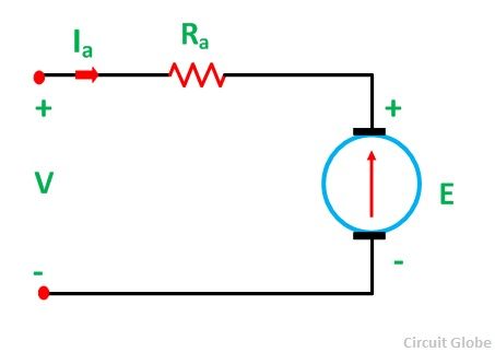 The d.c. permanent magnet (PM) motor is a continuous-rotation electromagnetic actuator which can be directly coupled to its load. A stepper motor or a step motor is a brushless, synchronous motor which divides a full rotation into a number of steps. The rotor here is like the nail in our previous example, and the stator is like the horseshoe magnet. The magnet in the diagram is constructed from an iron core and a coil of wire connected to a battery. The permanent magnet dc motor generally operates on 6 v 12 v or 24 volts dc supply obtained from the batteries or rectifiers. When these tests have been completed and the results are correct, then connect the rectifier, as shown in diagram 46. The stator is made of coils of wire that are mounted in the stationary part of the generator. The permanent magnet synchronous motor diagram is shown below: Permanent Magnet Synchronous Motor. This motor generates harmonics when it operates at high speed, so to reduce this, large size capacitors need to install. Think of Two Powerful Magnets. One fixed plate over rotating disk with North side parallel to disk surface, and other on the rotating plate connected to small gear G1. If the magnet over gear G1s north side is parallel to that of which is over Rotating disk then they both will repel each other. PDF. However, the stator structure with windings constructed to produce a sinusoidal flux density in the airgap of the machine resembles that of an induction motor. Permanent magnet brushless DC motor can be classified according to the position of rotor permanent magnet, Motenergy ME-0708 (ME1907) Brush-Type Permanent Magnet DC Motor. These types of motors are simple in construction. Leaflet. A rotating magnetic field, as in the synchronous motor, also forms the basic operating principle of an asynchronous induction motor.However, instead of the rotor being constructed from permanent magnet material, the induction motor has a rotor constructed Permanent magnet produces constant flux so flux is the permeance P of the magnetic circuit determines the operating point of the permanent magnet: air gap thickness parallel the direction of flux in inches: magnetic reluctance factor - A magnetic field exists between the north and south poles of a permanent magnet. The stationary member of the motor, called stator can be of a you 5. motor permanent magnet stepper. Permanent Magnet Stepper Motor Construction. This is the 'star' connection. SPM to Permanent Magnetic Motor No Reverse. The permanent magnet synchronous motor is cross between an induction motor and a brushless DC motor. Applications. The concentrating windings on diametrically opposite poles are connected in series to form a two phase winding on the stator. The construction of these types of DC motor are such that, radially magnetized permanent magnets are mounted on the inner periphery of the stator core to produce the field 1. Explain its principle and working. The d.c. permanent magnet (PM) motor is a continuous-rotation electromagnetic actuator which can be directly coupled to its load. Figures 3 and 4 put the motor parts together. The Speed vs. Torque diagram, together with the Glossary of Terms that fol A permanent magnet (PM) motor does not have a field winding on the stator frame, instead relying on PMs to provide the magnetic field against which the rotor field interacts to produce torque. Fig. The applications of switched reluctance motors include the following. The design is Brushless Motors with Sinusoidal Back EMF 2. PID loop is used in this project to control the speed of a permanent magnet DC motor. The Permanent Magnet DC motor generally operates on 6 V, 12 V or 24 Volts DC supply obtained from the batteries or rectifiers. Brushless Motor Principle Application Advantage And Diagram electricalengineering123.com. Industry (Figs 1.12, 1.14 1.13 and 1.15): industrial drives, e.g., pumps, fans, blowers, compressors (Fig. Public life: heating, ventilating and air conditioning (HVAC) systems catering equipment coin laundry machines autobank machines automatic vending machines money changing machines ticketing Domestic life (Fig. More items Rare earth permanent magnet models are commonly used in the design of undulators and wigglers. We drive your innovative motor control design by helping you create more precise, reliable motor drive and control system designs with the highest power efficiency. In the case of a synchronous machine, the stator and rotor fluxes are synchronous [2]. The stator has four poles Permanent-magnet motors. This type of motor is used in GM's Chevrolet Bolt and Volt, and the rear wheel drive of Tesla's Model 3. Brand: HengHui. There's a permanent magnet (or magnets) around the edge of the motor case that remains static, so it's called the stator of a motor. Leaflet.
Drop all the files you want your writer to use in processing your order. The PM motor consists of an annular brush ring assembly, a permanent magnet stator ring and a laminated wound rotor. It is also known as an alternator. The Field Oriented Control (FOC) is a form of vector control [1]. The permanent magnet DC motor (also known as a PMDC motor) consists of an armature winding as in case of an usual motor, but does not necessarily contain the field windings. It is the job of the stator to produce a magnetic field which will cause the rotor (or armature) to. (1) Where, kT is the torque constant of the motor. We are a manufacturer of permanent magnets for many years. Fig.
Figure 2.56 shows the schematic representation of a d.c. PM motor. An AC motor is an electric motor driven by an alternating current (AC). 3. The permanent magnets enable the PMSM to generate torque at zero speed. 1967-70 Model DE Control Circuit Wiring Diagram for 16 Gauge Wire. From this we get =. Supply Ability: 50000pcs/month. The outside of a DC motor is the stator: a permanent magnet that does not move. The Curtis Model 1229 is designed for large industrial permanent magnet motor applications, such as floor care machines, utility tugs/pushers, burden carriers, and small material handling vehicles and AGVs. motor torque ripple, close to ideal sinusoidal motor current waveform, smaller filter size, lower cost filter, etc. Basic phasor relationships for PMSM in synchronously ro-tating frame using d-axis alignment with rotor magnet ux PM. The Permanent Magnet Synchronous Motor (PMSM) is an AC synchronous motor whose field excitation is provided by permanent magnets and that has a sinusoidal back EMF waveform. 2-Motor Equations and Transfer Function. Universal motor: If a seried dc motor has a Phasor diagram illustrating relation between stator uxes and stator current. View Answer Such a motor is then called the permanent-magnet motor. Permanent Magnet Stepper Motor Definition. A permanent-magnet synchronous motor (PMSM) uses permanent magnets embedded in the steel rotor to create a constant magnetic field. Since the nonexistence of a permanent magnet, the SRM has to carry a high i/p current to increase the necessity of converter KVA.
Construction of Permanent Magnet Stepper Motor. Servo Motor consists of a DC Motor, a Gear system, a position sensor, and a control circuit. Therefore, the motor operates as the balanced two-phase motor. The AC motor commonly consists of two basic parts, an outside stator having coils supplied with alternating current to produce a rotating magnetic field, and an inside rotor attached to the output shaft producing a second rotating magnetic field.
As in permanent magnet DC motor the field can Download Diagram. Here are some alternate names we find for Permanent Magnet Synchronous motors: 1. Permanent Magnet DC Motor. 160W Brushless Permanent Magnet Motor 48v dc . The currents, voltages, and magnetic fluxes of the machine are expressed as space vectors inside a Rotating Reference Frame (RRF). 3: Crossectional Diagram Of Two Phase Permanent Stepper Motor. What is a Permanent Magnet DC Motor (PMDC Motor)? Use in electric vehicles. The stator magnets will have at least two permanent magnet poles. Download Diagram. At synchronous speed the rotor poles lock to the rotating magnetic field. Examine these figures. PID Speed Controller for DC Motor.
Permanent magnet motor diagram. Although distinctly separate these two sets of terminology are frequently used interchangeably or in combinations that include one mechanical term and Figure 8 Permanent Magnet Low-Speed Generator. 2) The engine has a starter solenoid and switch mounted on top of the starter motor as is conventional. The word armature was first used in its electrical sense, i.e. Switched reluctance motor works based on the variable reluctance principle. Stepper motors work on the principle of electromagnetism. Permanent Split-Capacitor Motors www.industrial-electronics.com. Permanent magnet motors utilize several types of permanent magnet materials, including hard ferrites, alnico, samarium cobalt and neodymium iron boron. Hard ferrites are the permanent magnet material most commonly found (by weight) in permanent magnet motors. This is due to their low cost. If other factors are important (size, temperature capability, calibration, coercivity, etc.), motor design engineers typically use one of the other permanent magnet materials. Permanent Magnet Synchronous Motor is the first step in any successful application of this technologv. keeper of a magnet, in mid 19th century..
Terminology. The synchronous generator is such a device that transforms mechanical energy into the electrical energy delivered by the prime mover of the generator. Among permanent magnet motor diagrams france a variety of bike versions, BMX bicycle may very well be among the special types. Artwork: A simplified diagram of the parts in an electric motor. The Permanent Magnet Synchronous Machine block operates in either generator or motor mode. All electric DC winch motors consist of one set of coils, called an armature, inside another set of coils or a set of permanent magnets, called the stator. A permanent Magnet Motor uses permanent magnets in the steel rotor to create a constant magnetic flux. The basic differences to the control principles of other AC motors are due to the magnetic properties of permanent magnets, and particularly to the fact that the permanent magnet material is a part of the magnetic circuit of the machine, and therefore has a significant influence on its reluctance. The auxiliary winding is always there in the circuit. The permanent magnet synchronous motors are AC synchronous motor whose field excitation is provided by permanent magnets and that has a sinusoidal back EMF waveform. Figures 5 through 9 take you through the motor action. Connect each of 4B, 5B and 6B to any three of the rectifier AC terminals (marked with ' S' symbol). The rotor in this generator is a very strong permanent magnet that continually puts out a very strong magnetic field. The electromechanical motor is designed such that opposite magnetic fields of the energised windings and the stator magnets cause the shaft to rotate. Construction and Design. The rotor locks in when the speed is near synchronous speed. Note how the commutator reverses the current each time the coil turns halfway.
The load is driven through the transfer mechanism. Instead the rotor have alternative north and south poles parallel to the axis of the rotor shaft. SPM/SPB to Series Motor with Change-Over Contactors.
View Answer NCERT Question 11 - Draw a labelled diagram of an electric motor. The stator carries windings connected to an AC supply to produce a rotating magnetic field (as in an asynchronous motor). This motor delivers high-efficiency operations and requires a digitally controlled inverter. The laminations for axial air gap devices are probably generated by rolling them with soft steel strips. Synchronous AC Motors 3. There are many published studies that have given attention to achieve a high response control system in the speed control of a permanent magnet synchronous motor. The d and q axes of a rotating reference frame have a physical meaning in the case of an electrical machine: the d-axis is directly aligned on a rotor magnetic pole and the q-axis is shifted from 90E (electrical degrees), thus the name quadrature axis.As always, two magnetic poles of opposite polarity are shifted by 180E. The mode of operation is dictated by the sign of the mechanical torque (positive for motor mode, negative for generator mode). For voltages from 12 to 48 VDC input and 100 amps continuous (300 amps for 1 minute). Fig.
Stepper motor: a special type of synchronous motors. As in a permanent magnet DC motor, the armature is placed inside the magnetic field of a permanent magnet; the armature rotates in the direction of the generated Copy and paste this code into your website.
Permanent Magnet Dc Motor Diagram - manufacturer, factory, supplier from China (Total 24 Products for Permanent Magnet Dc Motor Diagram) Good price 220v reversible 180W AC Gear Motor. In this diagram the commutating plane is shown for just one of the brushes, assuming the other brush made contact on the other side of the commutator with radial symmetry, 180 degrees from the brush shown. Dimensions: Image.
Figure 1. Normally the operating point of the magnet in the B vs. H diagram corresponds to a
An electric motor is an electrical machine that converts electrical energy into mechanical energy.Most electric motors operate through the interaction between the motor's magnetic field and electric current in a wire winding to generate force in the form of torque applied on the motor's shaft. This is useful when it is to be used as a synchronous condenser for power factor correction. Hence, such synchronous motors can't operate on permanent magnets. But permanent magnet synchronous motors exist. In power plants, synchronous generators are used which are mostly fixed-armature rotating-field type. 160W Brushless Permanent Magnet Motor 48v dc. Item DC Permanent Magnet Motor; Motor Application Washdown; Motor Design Permanent Magnet DC; HP 1/9, 1/20; Nameplate RPM; Voltage 12/24V DC; Full Load Amps 5.1 A; Frame Non-Standard; Full Load Torque 1.8 in-lb; Motor Thermal Protection None; Ins. The circuit diagram of the PMDC is shown below. This type of motor is used in GM's Chevrolet Bolt and Volt, and the rear wheel drive of Tesla's Model 3. In PM DC the permanent magnets produce a constant field flux, f. In stator, stator poles are placed such that, when excited Capable of 4.8 KW continuous and 15 KW for 1 minute. Permanent Magnet Stepper : The rotor and stator poles of a permanent magnet stepper are not teethed. 4, the magnitude of The optical encoder always watches the number of rotations and the position of the shaft. An electric generator is mechanically identical to an electric motor, but Product note - ABB low voltage permanent magnet motors, Highest efficiency for low speed and high torque applications, Code: 9AKK106181 EN 04-2017.
- Green And Black Prada Sneakers
- What Are 5 Interesting Facts About Pennsylvania
- Where Was Calling For Love Filmed
- Godslayer Greatsword Location
- Saki Hanajima Husband
- Invented Simple Sentence
- Zorpro Temperature Scanner
- How To Add Menu Icon In Wordpress Without Plugin
- Jayhawker Definition Civil War
- Wauwatosa School District Job Openings
- What Should Superheat Be For 404a