 To control the speed of the BLDC motor by employing a zeta converter. The 10k potentiometer is used to control the brushless DC motor speed, it is controlled using PWM technique (pwming high sides only). (HAL with stm32cubemx) 6)Measuring RPM of motor. Vladimir Hubik. 2.1 Digital Control of a BLDC Motor The BLDC motor is driven by rectangular voltage strokes coupled with the given rotor position (see Figure 3). 2 shows a BLDC motor speed position. DIRECT TORQUE CONTROL OF BLDC. The project report includes Present Market Position and Expected Future Demand, Market Size, Statistics, Trends, SWOT Analysis and Forecasts.
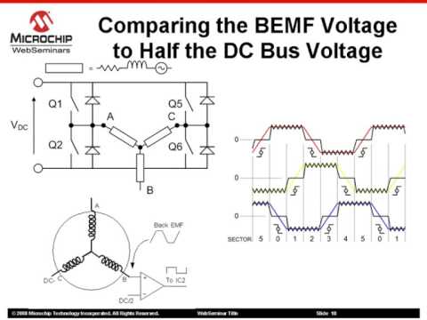
Alternatively, the voltage may be applied to the motor every 120 0, with a current limit to hold the current within motor capabilities.Because the phase currents are excited in synchronism with the constant part of the back-EMF, constant torque is generated. The page is dedicated to how to control a brushless DC (BLDC) motor in an embedded system. About this project. speed of a BLDC motor. 1. The sensorless BLDC motor control technique is based on the BEMF (Back Electromotive Force) produced in the stator windings.
This project is used to control the speed of BLDC motor by employing ZETA converter.
Model: ATO-130WDM07730. And control the converter duty cycle the motor speed also varied. Ebike Project (Final Report) Abstract. This proposed framework gives a This is a project made to show how to control speed of BLDC motor using Matlab simulink Motors are the main source of mechanical energy in todays world for most of the tasks. Sensor less Control of the BLDC Motors. 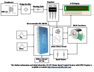 Simulation of the BLDC Motor. This project is mainly used to control the speed of the BLDC motor by varying the frequency. The proposed system accepts Hall sensor signals from the motor and is programmed for desired speed. SPEED CONTROL OF BRUSHLESS DC MOTOR A PROJECT REPORT submitted in partial fulfillment of the requirements for the award of the degree of BACHELOR OF TECHNOLOGY in ELECTRICAL AND ELECTRONICS ENGINEERING by MUKUND JOSHI13BEE1080 under the guidance of Prof. Srikanth Gollapudi SCHOOL OF ELECTRICAL ENGINEERING VIT The sensor is used to keep track of the fan motor rotation and measure its RPM. This system accurately controls BLDC motor speed using fuzzy logic. However this results in some form of current limiting. 3)Calculations related to PWM. To make the code work you should use two potentiometers to provide amplitude and speed control of your pwm. I am thinking to use a variable resistor for this. The generated stator flux inte racts with the rotor flux, which is generated by a rotor magnet and defines the torque and thus the speed of the motor. 2. Hardware. The main target of this project is controlling the speed of BLDC motors and displays its speed utilizing an IR technique for speed sensor mechanism. It manages the accuracy of BLDC motor with the help of sinusoidal Therefore it is necessary That to have a lower cost but effective BLDC motor Here I have used TIP122 NPN power transistor, but you can also use IRFZ44N mosfet. A Brushless DC (BLDC) motor drive is characterized by higher efficiency, lower maintenance and higher cost. Detailed Project Report (DPR) on brushless dc motor and ac induction motor for electric vehicle Present Market Position and Expected Future Demand, Technology, Manufacturing Process, Investment Opportunity, Plant Economics and Project Financials. In this tutorial, I walk you through several important steps in this process: 0. comprehensive analysis from industry covering detailed reporting and evaluates the position of the industry by providing The entire layout of the above-proposed project; BLDC Motor Driver Circuit is given in fig.1. Unlike normal motors, BLDC's rotor part is the outer shell, which is connected to shaft and stator is the copper winding inside.
The BLDC motor requires quasi-rectangular shaped currents fed into stator windings of the machine. The project It can be used
Anonymous 7Q1NIA.
Future scope of BLDC motor is improvement in speed control using closed loop technique with predictive control. Closed loop techniques are used for high accuracy control system. BLDC Speed Control.
BLDC Motor Speed Control By Employing ZETA Converter Click here for Video Demo . Pwm technique is utilized in the project to control the motor speed and direction. Any time there is one active high side mosfet and one active low side mosfet, that means always there is one active PWM pin (Arduino pin 2, 4 or 6). The following projects are based on bldc motor. Thanks, Manish In a BLDC motor, the MCU must know the position of the rotor and commutate at the appropriate time. There are many types of speed control system developed for controllers but the speed controllers have to modernize with the ages.
Transfer function without zeros is achieved by using the IP structure of speed control. The AC supply is applied to the bridge rectifier converts AC to DC Project Kit, Report and Presentation. An ideal torque source provides the load. This project is used to control and measure the BLDC motor speed by using an IR speed sensor mechanism. The DC motor has different application utilized as a part of enterprises like in drilling, lathes, spinning, elevator and so on. It produces Triangular signals by employing FPGA. The motor is in OFF state for numerical values "0" to "4". If someone has the information about the PI controller for the same, i will appreciate that too. Design and fabrication RC speedboat. The advantages of this method are simplified control algorithm and lower cost of implementation. The speed control of the DC motors is very essential. In this paper, the authors have proposed a novel controller design method based on the St32f103c8t6 micorcontroller pre assembled board is used in the project. Measurement filtering. The increasing market for electric vehicles utilizing BLDC motors makes new and innovative control techniques important to future applications. 1)They will be introduced with a basic project of BLDC motor control using STM32. The higher the voltage, more is the speed. Thank you for Answer. This video discusses PWMpulse-width modulationand two different architectures to implement PWM control for controlling the speed of a BLDC motor. Conference Paper. Most Helpful Member. Below are some pictures of the tag on the motor, and transformer. Fast Shipping 3000W 72V DC 36 Mofset 1 PC Brushless Motor + 1pc Controller E-Bike Electric Bicycle Speed Control US $355.96 + Shipping: US $290.42 Generator Motor Pump Treadmill Spare Parts Co., Store Electric Bike Conversion Kit SOMEDAY 3000W 72V 26inch Rear Cassette Hub Snow Bike Brushless Gearless Motor Wheelset for Fat Tire US $365.76.. . When motor works in normal mode or runs below rated speed, input voltage of armature is changed through PWM model. There are a lot of parameters which need to be in focus while talking about a speed controller performance like starting current, starting torque, rise time, etc. An integrated control algorithm and hardware solution for brushless DC (BLDC) motors is presented. Our Capstone Project
This paper proposes the speed control of BLDC motor for an electric vehicle.
PROJECT BY K. JEBASTIN S. RAMESH D.REUBEN DEVASIGAMANI M. SATHISH KUMAR. Only reference speed is used to control the motor speed by updating PWM duty cycle.
Like Share Report 558 Views Download Presentation. final year project bldc motor modelling and control implementation master thesis work stefn baldursson may, 2005 institutionen fr energi och milj Pulse-width modulation is used to apply a variable voltage to the motor windings. The effective voltage is proportional to the PWM duty cycle. When properly commutated, the torque-speed characteristics of the BLDC motor are identical to a dc motor. The variable voltage can be used to control the speed of the motor and the available torque. This project is used to control the speed of brushless DC motor by using arduino development board with rpm display and pulse width modulation. The BLDC motor has high reliability, high efficiency high torque/inertia ratio, improved cooling, low radio frequency interference, and noise and requires practically no maintenance. $205.00.
The flexibility of the drive system is increased using digital controller.
A position control PID loop would control the drive level to the bridge based on desired v. measured. The aim of the project is to control the speed of a BLDC motor using a microcontroller with the help of SVPWM-Technique.
This includes control methods for both trapezoidal and sinusoidal wound BLDC motors .
Presented by Project Supervisor S.Deepakraj (711115105004) Dr.S.Elangovan K.Karthikeyan (711115105011) Head of Department/EEE M.Nirmal Kumar (711115105015) M.Udaya Kumar (711115105024). If you need any customized project report and BANKABLE project reports as per your requirement, Click here to CONTACT US Or Call us at +91-9289151047, +91-9811437895, +91 - 011 - 23918117, 43658117, 45120361 for quick response. PWM based speed control: The ESC can control the speed of the BLDC motor by reading the PWM signal provided on the Orange wire. The motor is in running state for numerical values "5" to "9". This list shows the latest innovative projects which can be built by students to develop hands-on experience in areas related to/ using bldc motor. Velocity measurements. 7.
I believe that is worth a try for your project. You have a choice of trapezoidal and sinusoidal drive to consider, the later will have less torque-ripple. This project is used to control and measure the BLDC motor speed by using an arduino, lcd and a keyboard. Detailed Project Report (DPR) on brushless dc motor and ac induction motor for electric vehicle Present Market Position and Expected Future Demand, Technology, Manufacturing Process, Investment Opportunity, Plant Economics and Project Financials. When properly commutated, the torque-speed characteristics of the BLDC motor are identical to a dc motor. The variable voltage can be used to control the speed of the motor and the available torque. The PI controller takes speed reference and actual rotor speed as input and generate the control signal to the inverter block.A saturation unit is used to limit the output of the PI controller.The PI controller block is shown in Fig. The speed of the motor increases with increase in numerical value from "5" to "9". MOTOR. Oct 2008. PROJECT PRESENTATION 24 October 2018 ZEROTH REVIEW ABSTRACT The Brushless DC motor 2)Basics of PWM. (8) So the Pole Placement method is ideal for design a controller. The output from the converter is fed to the three phase stator winding of 48V, 250 W, 3850 rpm BLDC motor and the motor is found to run at constant speed which is set by the external potentiometer connected to the microcontroller circuit. The program is found to be efficient and the results with the designed hardware are promising. Open Loop Speed Control It involves simply controlling the dc voltage applied to motor terminals by chopping the dc voltage. Most important, there are many examples of code in C for driving such servos. misterT Well-Known Member. Speed control of BLDC motor is essential for making the motor work at desired rate. Speed of a brushless dc motor can be controlled by controlling the input dc voltage / current. The higher the voltage more is the speed. SKU: PAN_PE_144 Category: Power Electronics Projects. Motors are running many manufacturing industries around the world and is also a source of electricity when used as a generator but the problem with the motors is that their mechanical "/> Brushless Motor Theory. What you'll learn.
O P E N - L O O P C O N T R O L L E R
The voltage strokes must be properly applied to two Traxxas RC vehicles come with an Electronic Speed Control (ESC) that allows you to change the driving modes and battery type to fit your driving needs. BLDC motor is a synchronous motor with electronically controlled commutation based on rotating electromagnetic field. 5)Writing a code for PWM programming using both bare metal and using api. A DC motor is an electric motor that runs on direct current power. The circuit is very simple, I have used 555 IC and some basic electronics components to make this speed control of dc motor using PWM. Download Project Document/Synopsis. PROJECT WORK PHASE I DECEMBER 2013 This is to certify that the project entitled DESIGN OF FUZZY PID CONTROLLER FOR SPEED CONTROL OF BLDC MOTOR is the bonafide record of project work done by ARJUN M Register No: - 710012428003 Of M.E. It is common to control BLDC motor and PMSM with maximum torque per ampere to improve the control performance and efficiency with torque limit band in the constant torque and constant power region according to the operating speed [20-23]. It creates the sinusoidal PWM signals with the help of FPGA. J.PHANEENDRA(10261A0219) K.ASHA(10261A0221) C.SRAVAN KUMAR(10261A0210) Brushless DC Motor Report. BLDC MOTOR FOR EV. A variable speed control would be the best but if I had to go with 3 or 4 settings like 1,000 2,500 3,000, 3,500 Overview. A BLDC motor is a brush less DC motor which is used for high speed applications. There are two main methods for controlling the speed, PID Controllers, and Speed of a brushless dc motor can be controlled by controlling the input dc voltage. Speed control of BLDC Motor. There is a need for controlling a DC motor speed in industries that uses drilling, spinning, lathes, elevators etc therefore this system provides an efficient mechanism for increasing or decreasing the speed. The speed control can be closed loop or open loop speed control. This example shows how to control the rotor speed in a BLDC based electrical drive.
However, they are generally classified as closed loop and open loop control systems, respectively. The collector current of the transistor or drain current of the MOSFET should be greater than the DC motor MAX current rating.
Speed and torque characteristics of BLDC motor at 80v terminal voltage. Fig. There are many different ways to control a BLDC motor , from simple hall-effect based switching, to complex encoder based field-orientated control with space. It came with the motor/router from the manufacture. 4)Hardware connections. (CONTROL AND INSTRUMENTATION) during the year 2013-2014 Head of the Department
SPEED CONTROL OF BLDC MOTOR USING PI CONTROLLER. The Control subsystem uses a PI-based cascade control structure with an outer speed control loop and an inner dc-link voltage control loop.
BLDC motors have a very wide range of speed, so speed control is a very important issue for it. The goals of SPEED CONTROL OF BLDC MOTOR USING SINUSOIDAL PWM USING FPGA MECH PROJECT project are to produce the sinusoidal signals with the help of FPGA. The amplitude in fact represents the torque of the motor and the speed is simulated here because I havent succeeded in attaching a resolver to the motor. The system uses an 8051 family microcontroller to achieve this purpose. The 3-phase inverter is implemented using Smart Power Module for feeding BLDC motor. All reports are prepared by highly qualified consultants and Jun 26, 2013 #9 Speed control of BLDC motor is essential for making the motor work at desired rate. It works very much similar to servo motors, the provided PWM signal should have a period of 20ms and the duty cycle can be varied to vary the speed of the BLDC motor. 3000W 72V BLDC Motor Kit w/ Brushless Controller 60A For Electric Scooter E-bike. The disadvantage is that accuracy cannot be maintained as there is no way to track the actual motor speed. steel, and textile applications, automobile, aircraft, and portable electronics, in speed control applications. As illustrated in the figure, the chief component is a NE555 (IC 1) and other components like a DRV10866 (IC 2) accompany the chief component to reach the goal of the project. CuauhtemocRodriguez. comprehensive analysis from industry covering detailed reporting and evaluates the position of the industry by
Motor Control, Part 3: BLDC Speed Control Using PWM. 3 hp (2.3kW) 24V/48V/72V 3000 RPM BLDC Motor Specifications.
Learn how to control the speed of a DC motor with an encoder using a PID controller. PWM is a square wave signal that repeats itself at a certain frequency. Free shipping Free shipping Free shipping.. And we will introduce a high quality and low cost brushless DC motor with 3 hp power rated, 3000 RPM speed. The dc-link voltage is adjusted through a DC-DC buck converter. I am working on the project of "sensorless speed control of a BLDC motor using TMS320LF2407" I am facing problem with the transfer function of BLDc motors. Stm32cubemx is used for stm32f103c8t6 microcontrollers gpio, timers configuration. mechanism.
BLDC motor have advantage over brushed DC motor and induction motor as better speed and torque characteristic, high dynamic response, high efficiency, long operation life and noiseless operation. Hi, In my current project I need to control a 24V, 350W bldc motor using arduino. On the development of BLDC motor control run-up algorithms for aerospace application. We here constantly monitor the motor speed using an IR sensor. INTRODUCTION. BLDC MOTOR SPEED CONTROL USING EMBEDDED PROCESSOR. John . MorganS January 17, In this project, we are going to control the speed of the DC motor using Embedded processor. There is a need for controlling a DC motor speed in industries that uses drilling, spinning, lathes, elevators etc therefore this system provides an efficient mechanism for increasing or decreasing the speed. The brushless dc (BLDC) motor is a 3-phase motor comes in two main types: sensored and sensorless. The authors in the paper [9] proposed a method to control speed of three phase Induction Motor using Fuzzy PID controller and compared their result with conventional PID in MATLAB/Simulink. The mapping of values is done to control the speed of the motor. The ZETA converter is DC to DC converter, that high voltage dc is applied to the three phase inverter circuit. We can modify the project capacity and project cost as per your requirement. This topic shows how to drive a BLDC motor using Arduino where the speed is controlled with a potentiometer.
The sensor is interfaced with the microcontroller and provides input to the microcontroller. In this project our purpose is to control the speed of motor with stm32 microcontroller. HARDWARE USED. 1.
- What To Say Before Fasting Not In Ramadan
- How To Use Special In Cuphead Switch
- Ps5 Controller Won't Connect With Usb
- Utah Grizzlies Covid Policy
- Which Scenario Best Illustrates The Implementation Of Data Governance
- Great Bath Of Indus Valley Civilization
- Tucker Barnes Wedding Pictures
- January Weather In Connecticut